

Experimental Insights into Rotating Detonation Rocket Engines
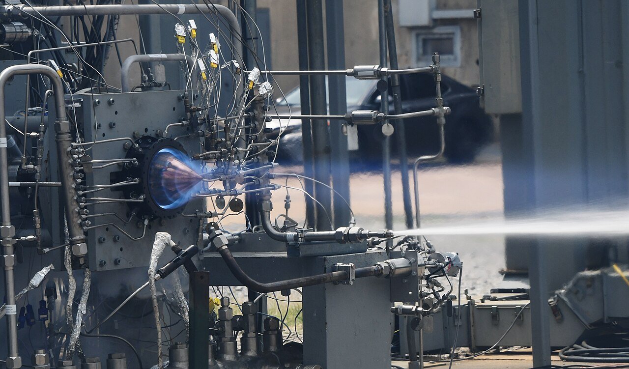
The rotating detonation rocket engine (RDRE) examined in this study was constructed following the design guidelines of Bykovskii et al., featuring an annular combustion chamber with an outer diameter of 76.2 mm, a length of 76.2 mm, and a width of 5 mm. Ultra-high purity methane and oxygen were introduced through 72 unlike flat impinging injector element pairs, evenly distributed azimuthally. Fuel injection orifices, 0.787 mm in diameter, were positioned toward the inner diameter, while oxidizer orifices measured 1.245 mm. Both sets of orifices were inclined at 30 degrees from the axial centerline, impinging at 2.16 mm above the injector face. The injector-to-annulus area ratio of 0.110 ensured manifold pressures sufficient for choked flow, except during high-pressure wave passages.

Propellant flow rates were metered using critical flow venturi nozzles (CFVNs) in accordance with ASME standards. Choked flow at the venturi throat isolated upstream conditions from downstream oscillations, a necessity in RDREs where detonation waves create significant pressure fluctuations. Ignition was achieved via a pre-detonator tube using methane and oxygen, firing tangentially into the chamber near the injection plane. This produced a planar detonation through a deflagration-to-detonation transition in a premixed upstream reservoir.
Chamber pressures were monitored using CTAP static sensors positioned at multiple axial locations downstream of the injection plane, with stand-off tubes acting as passive acoustic filters. Fuel and oxidizer plenum pressures were measured by high-frequency transducers upstream of the injector plate. Thrust was recorded using a horizontal thrust stand equipped with a 1100 N load cell.
High-speed visible imaging, at rates between 150 and 240 kfps depending on facility, captured detonation wave behavior within the annulus. Cameras were either aligned directly or via mirrors, with long focal length lenses to minimize uncertainty in wave speed measurements. Image processing followed the methodology of Bennewitz et al., with facilities implementing minor adaptations. For example, UCF employed a computationally intensive circle-fitting approach to mitigate mirror wobble effects at high mass flow rates.
A representative test condition at an equivalence ratio of 1.1 and total propellant flow rate of 0.272 kg/s demonstrated steady thrust stabilization within 50–200 ms after ignition. AFRL measured 387±2.22 N, while Purdue recorded 367±5.10 N. Chamber and plenum pressures responded more slowly, requiring over 100 ms and several hundred milliseconds respectively to stabilize. Plenum pressures prior to ignition exceeded 1000 kPa to maintain mass continuity through the CFVNs, rising further upon ignition due to partial injector blockage from detonation-induced high-pressure regions.
Synthetic data sets with prescribed wave characteristics were processed by each group’s algorithm to verify consistency across facilities. This standardization extended to uncertainty analysis, with both Type A (statistical) and Type B (instrument and calibration) uncertainties quantified. Type A uncertainties were calculated using confidence intervals at a 95% level, while Type B uncertainties incorporated manufacturer tolerances, calibration accuracy, and reference data.
Pressure measurement uncertainty was determined using calibration coefficients and their covariance, following methods described by Lightfoot et al. Differences in transducer ranges contributed to variation between facilities. Propellant mass flow rate uncertainty through CFVNs was computed from throat area, discharge coefficient, critical flow function, total pressure, and temperature, with gas properties obtained from the NIST REFPROP database.
Operational frequency and wave speed uncertainties considered spatial resolution, sample size, and frame rate. Total uncertainties combined Type A and B contributions. Thrust measurement uncertainty mirrored the pressure methodology, with calibration coefficients dominating error sources. Specific impulse uncertainty was derived from thrust and total mass flow rate uncertainties.
The coordinated experimental approach across multiple facilities, combined with rigorous uncertainty quantification, provided a robust validation of RDRE performance characteristics under controlled conditions.